9 Results
View results:
Sort by:

If members aligned in space meet in a node, the local x- or y-axes of the members do not lie in one plane, since the local z-axes are aligned in the plane of gravity.

General thin-walled cross-sections often have asymmetrical geometries. The principal axes of such sections are then not parallel to the horizontally and vertically aligned axes Y and Z. When determining the cross-section properties, the angle α between the center-of-gravity axis y and the principal axis u is determined in addition to the principal axis-related moments of inertia.

DXF layers of ground plans cannot be used directly in FEA programs because only the outer contours of the elements (walls, ceilings, and so on) are available in the drawing. The FEM programs require system axes, but only the outer contours of the elements (walls, ceilings, and so on) are available in the DXF drawing.
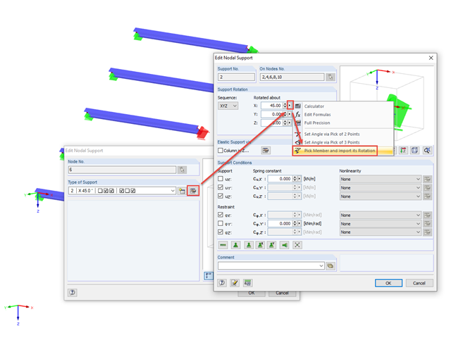
If you want to orient a nodal support to the member axes of the connecting member, the easiest way to do this is to use the "Pick Member and Import its Rotation" function.
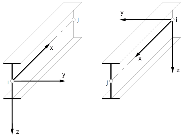
In spatial structures, the member position plays an important role in terms of determining internal forces. The orientation of member axes can be defined either by a global cross-section rotation angle, or by a specific member rotation angle. These two angles are added to determine the position of the main axes of a member in a 3D model.
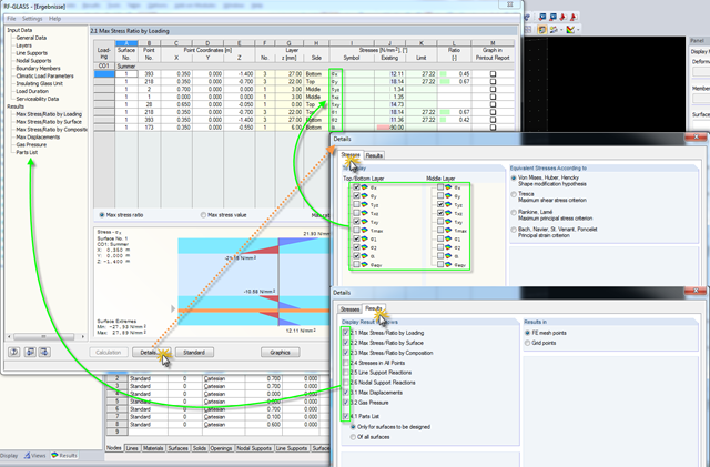
Click the [Details] button in RF-GLASS to select the results to be displayed. In order to get a better overview for the result evaluation, you can select the individual stress graphics (principal stresses, stresses oriented to axes, shear stresses) as well as various result windows. This way, you can show only the results you require.
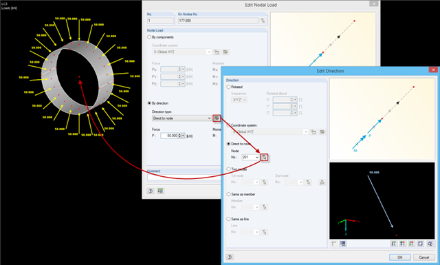
When defining nodal loads, you can rotate the load using several simple options: ~ Rotation by angle around the global coordinate axes in a specific order, ~ Alignment with a user-defined coordinate system, ~ Direction to a particular node, ~ Alignment by means of two nodes, ~ In the direction of a member/line.
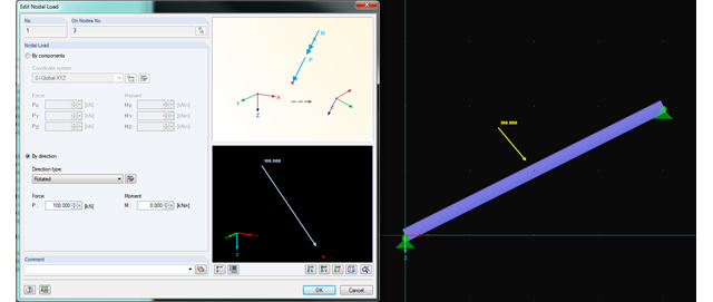
In RFEM and RSTAB, you can now rotate nodal loads or apply them on member axes. Thus, inclined members can also be loaded with nodal loads perpendicularly or along the member axis.
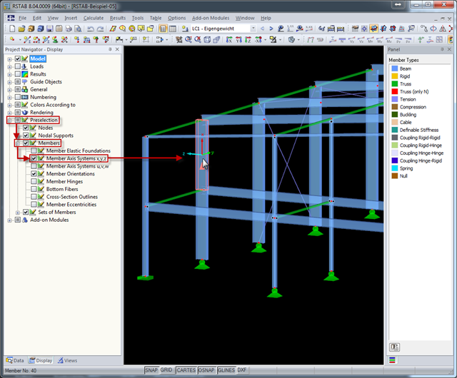
The local coordinate system of a member is particularly important when defining member end releases and member nonlinearities. The definitions follow the orientation of the axes. You can temporarily adjust the visibility of these member axes by means of preselection.